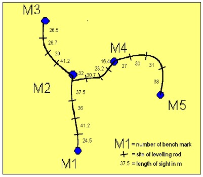
ON CALIBRATION OF ZEISS DINI12Dr. Mikko TAKALO, Paavo ROUHIAINEN, Pekka LEHMUSKOSKI and Veikko SAARANEN, FinlandKey words: Levelling, digital level, system calibration, type testing. AbstractThe calibration of the digital levelling system consists of the type testing and the calibration of the instrument-rod system. In this case the type testing includes some field tests. The system calibration includes the comparison of the difference of rod readings with true height differences. In the Finnish Geodetic Institute (FGI) we have investigated the precision of the digital levelling system (Zeiss DiNi12) and the spirit levelling method (Wild N3) with the simultaneous measurements at a new test field in Metsähovi. The results showed that the precision of the Zeiss DiNi12 was, significantly, better than that of the Wild N3. For the system calibration of the digital levels a comparator is under construction. The comparator will apply components of the existing FGI vertical laser rod comparator and realize, simultaneously, the rod scale and the system corrections. Some preliminary measurements to calibrate the Zeiss DiNi12 system have been carried out and the effect of the single non-typical line correction was discussed . INTRODUCTIONSince the launching of the first digital levelling system Wild NA2000 a lot of studies on the digital levels have been carried out (REITHOFER 1993; MAURER; SCHNÄDELBACH 1993; etc.). The calibration of the instrument-rod system, i.e., the system calibration of the digital level is displacing the rod scale calibration. RÜEGER and BRUNNER (2000) discussed in their article routines for type testing of the digital levels including following items: Repeatability at different sighting distances; effect of obstructions; temperature response, system precision, effect of light intensity, rod calibration and system calibration. In autumn 2000, the type tests of the Zeiss DiNi12 were started in the Finnish Geodetic Institute (FGI). During the first two months of the year 2001, the preliminary system and rod scale calibrations of the Zeiss DiNi12 were carried out using and utilizing the FGI vertical laser rod comparator (TAKALO 1997). FIELD TESTSMetsähovi Test fieldIn order to determine the line levelling accuracy of the Zeiss DiNi12 the Metsähovi test field (Fig. 1) was established. The field locates in the wooded area near by the Metsähovi
Fig.1. The Metsähovi test field for precise levelling instruments
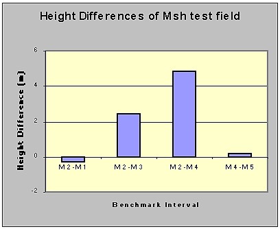
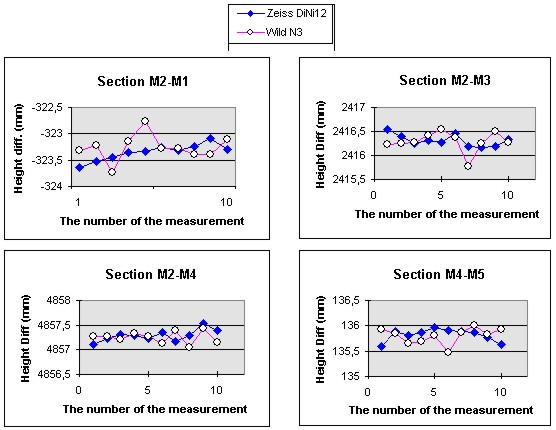
Fig. 2. Height differences of each interval in the Metsähovi test field. Space Geodetic station in Southern Finland. The field consists of five bench marks forming four intervals. All sites for rods are small bolts set on bedrock, boulders or support and all bench mark bolts are set on bedrock. The levelling roads are partly of sand, partly of rock and the total length of lines is 0.98 km. MeasurementsThe precision of the both levelling systems was determined as follows: Each bench mark interval from setup to setup was simultaneously measured with the Zeiss DiNi12 and with the Wild N3. The 3 m long bar code invar rods and the conventional 3 m long invar rods were used. In all, five fore and back measurements were carried out on the 7.-10,.13. and16. November, 2000. The weather conditions were favorable for precise levelling (cloudy, air temperature 2-7ºC). ResultsThe measured height differences of each bench mark interval are given in Fig. 3.
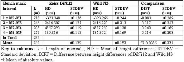
Fig. 3. Simultaneous measurements in the Metsähovi Test Field. The mean of the measured height differences of each bench mark interval and their standard deviations are given in Table 1. Table 1. Results of the simultaneous levellings with Zeiss DiNi12 and Wild N3 in the Metsähovi test field. Number of measurements is 10.
The standard deviations
Hence, according to Deutsche Norm DIN 18723 part 2 the accuracy with 95% confidence lies between following limits
The standard deviation of the Zeiss DiNi12 is significantly smaller than that of the Wild N3, because the Fisher test value
is with the 95% confidence larger than the critical value
On the contrary, the height differences between the instruments do not differ, because with 95% confidence the Student t-test value for the difference (DIFF) of the instrument means
is smaller than the critical value
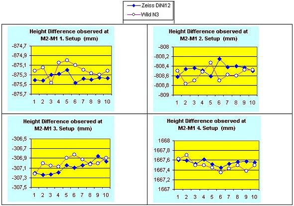
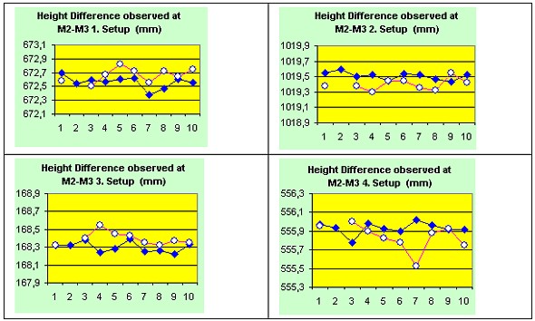
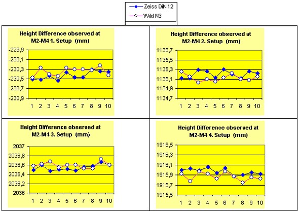
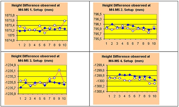
When considering the results of measurements by setups (Figs. 4-7), we can recognize some systematic sequences between the instruments.
Fig. 4. The height differences observed at the setup nos. 1, 2, 3 and 4 of the section M2-M1.
Fig. 5. The height differences observed at the setup nos. 1, 2, 3 and 4 of the section M2-M3.
Fig. 6. The height differences observed at the setup nos. 1, 2, 3 and 4 of the section M2-M4.
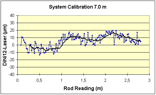
Fig. 7. The height differences observed at the setup nos. 1, 2, 3 and 4 of the section M4-M5 in the Metsähovi test field. According to the setup observations (Figs. 4-7) we can state that the precision of the Zeiss DiNi12 is better than that of the Wild N3. SYSTEM CALIBRATIONNowadays, approximately, 30-40 digital levels of different type are in use in Finland. Thus the need for calibration is evident and many users ask: "How reliable are the rod readings of the digital levelling system and what are the restrictions and the real accuracy of the system". The system calibration, in which the differences of the rod readings are compared with the true differences determined with the laser interferometer (TAKALO 1999), tells us about the reliability of the digital levelling system. Also the accuracy of the digital levels can be derived from the residuals of corrections. The comparator for the digital levels is now under construction in the FGI. The calibration system will partly apply the existing vertical laser rod comparator and make possible the simultaneous calibrations of the rod scale and the instrument-rod system. With the comparator we can, now, use 1.7 m and 7.0 m sighting distances. In the future we hope to expand our sighting distances with plain mirrors. Some preliminary system calibrations of the Wild NA2000 instrument with a fiber glass bar code rod GPCL4 using 1.7 m sighting distance (Fig. 9) and of the Zeiss DiNi12 using 1.7 m and 7.0 m sighting distances (Fig. 11 and 12) were carried out. When we had calibrated the rod scales with the FGI vertical laser rod comparator, results revealed non-typical errors both in the Zeiss DiNi (Fig. 10) and in the Wild bar code scales (Fig. 8). Many of them are out of standard given by the DIN 18717, which specifies a tolerance of ± (0.02mm+20ppm) for an arbitrary rod interval at 20° C.
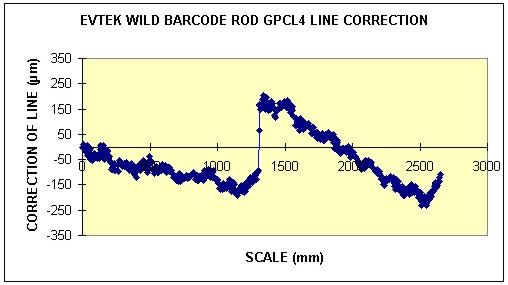
Fig. 8. Line correction of the Wild NA2000 barcode rod GPCL4.
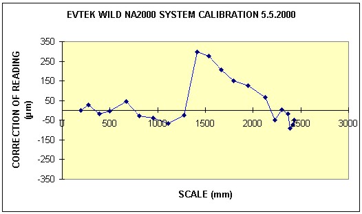
Fig. 9. System calibration of the Wild NA2000.
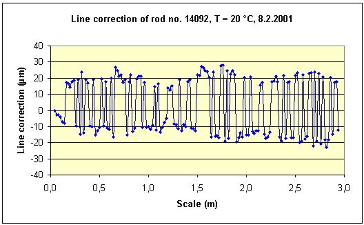
Fig. 10. Line correction of the Zeiss DiNi coded rod no. 14092.
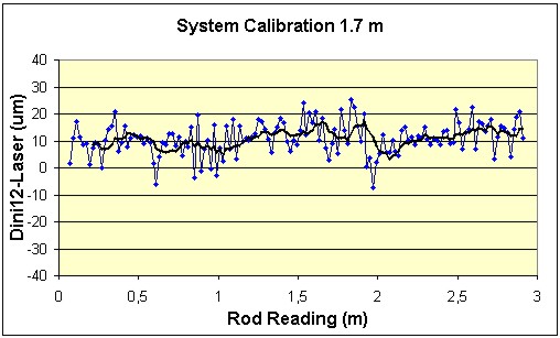
Fig. 11. System calibration of the Zeiss DiNi12 using 1.7 m sighting distance.
Fig. 12. System calibration of the Zeiss DiNi12 using 7.0 m sighting distance.
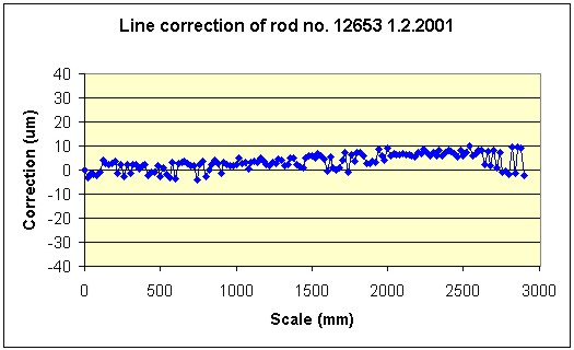
Fig. 13. Line correction of the Zeiss DiNi coded rod no. 12653. As shown in Fig. 8, a big jump of line correction, app. 0.3 mm, causes a similar jump in rod reading of the Wild NA2000 (Fig. 9). The origin of this jump is from a poor junction between two sections of the fiber glass rod Wild GPCL4. The line corrections of the Zeiss DiNi coded rod no. 14092 (Fig. 10) are unexpected large compared to the corresponding of a "normal" Zeiss DiNi coded rod no. 12653 (Fig. 13), but the influence of big line errors is minute as shown in Figs. 11 and 12. CONCLUSIONSThe simultaneous measurements with the digital level the Zeiss DiNi12 and the spirit level Wild N3 in the Metsähovi test field result that the precision of the Zeiss DiNi12 is better than that of the Wild N3. When considering the results of bench marks intervals, no systematic effect was found. On the other hand, the results of single setup indicated some systematic behaviour. The simultaneous calibration of the digital levelling system Zeiss DiNi12 and the bar coded rod showed that even big graduation errors of the rod can have a small effect on the rod readings. REFERENCESMAURER, W., SCHNÄDELBACH, K, 1993, Bestimmung der Systemgenauigkeit der digitalen Nivelliere NA2000/NA3000 (Determination of system Accuracy of the Digital Levels NA2000/NA3000). In Festschrift ´Schelling'. Mitt.geod.Inst.TU Graz, 78: 139-147, 1993. REITHOFER, A., 1993, Überprüfung des Digitalnivelliersystems Wild NA3000/GPCL (Calibration of the Digital levelling System Wild NA3000/GPCL). In Festschrift ´Schelling'. Mitt.geod.Inst.TU Graz, 78: 33-36, 1993. RÜEGER, J.M., BRUNNER, F.K., 2000, On System Calibration and Type Testing of Digital Levels. ZfV 4/2000. TAKALO, M., 1997, Automated Calibration of Precise Levelling Rods in Finland. Rep. Finn. Geod. Inst., 97:3. Helsinki 1997. TAKALO, M., 1999, Verification of Automated Calibration of Precise Levelling Rods in Finland. Rep. Finn. Geod. Inst., 99:7. Helsinki 1999. CONTACTMikko Takalo, Reseacher, Dr.Tech, Paavo Rouhiainen, Reseacher, M.
Sc., 22 April 2001 This page is maintained by the FIG Office. Last revised on 15-03-16. |